OH2NLT
Personal Home Page

OH7SV / OH2BKU
![]()
Personal
Home Page


OH2NLT Personal Home Page
|
 
 |
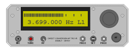
Direct conversion HF radio with DDS frequency synthesizer is very interesting concept. OH7SV and OH2NLT are experimenting with such rig. Full stories will become available when project matures. Here we have some preview pictures and material.
Project History
Matti OH7SV have had an idea for a long time about direct conversion receiver based on multiplexer mixer. The mixer principle is well known in measurement technology forming a lock-in detector and the commutating filter. It is a very efficient method to recover signals buried in noise. Today it is possible to implement the same principle in RF frequency range. Matti outlined this picture of multiplexer mixer receiver principle in 1998. After that Matti have been more or less QRT from 1998 until our project started.
I OH2NLT have had also long QRT about 12 years. Only some occasional mobile QSOs during this period. My activity woke up last autumn when technical class amateur license got full HF rights. I started to think to build home made HF rig. I had several discussions with Tane OH2UG about this subject. Tane had done some interesting experiments already 1997 with DSP (Digital Signal Processing) and so called Third-Method SSB HF Transceiver. Article about Third Method has published in Radio Communication magazine in 1996. Tane provided me lots of material about his experiments. I was also interested in direct conversion method. I searched material about this subject. I found very good article series about Software-Defined Radio published in QEX magazine, which describes direct conversion DSP radio. Link to QEX articles.
Our "Project Marketing Manager" Jussi OH7TE is old friend of Matti. I met Jussi with my first HF CQs. After some discussions with Jussi he connected me with Matti. This happened early 2004. Dust was blown off from dormant Matti’s project. During past three months we have done working prototype of the Direct Conversion HF SSB transceiver what is presented here.
Next steps will be:
- fine tune current hardware design
- implement needed features into rig control firmware
- build metal housing for rig
- finalize 20-30W PA
Possible future steps
- build 100-200W linear amplifier in separate box
- apply DSP technology for audio filters
Diary
First QSO with DC radios at both ends held 25.04.2004 between OH7SV and OH2NLT. OH7SV had first DX QSO with about 10W output. 02.05.2004. Also other operators have successfully tested the DC Rig. OH2NLT quick and dirty power amplifier upgraded to 30W 04.05.2004. SWR and Power meter functions added to the rig 14.05.2004. Software for power and swr meter functions is not yet fully tested.
Pictures of PC Boards
DC Radio 1
DC Radio 2
Polyphase Network
AF band pass filter
RF band pass filter | RF
band pass filter with other coils
DDS Board front
DDS Board back
DDS design
SWR Bridge prototype board Front
| Back
Schematics & software
Only non commercial use of presented material is
allowed. Copyright OH7SV and OH2NLT. Material is presented as is and no
responsibility is taken of direct or indirect damages. Building and using
radio transmitter without amateur license is not approved.
Direct Digital Synthesizer Local Oscillator and
transceiver control
DDS Synthesizer & rig
control block diagram
DDS board schematics |
DDS
Board Layout Top | DDF Board Layout Bottom
DDS & rig control test
software v1.0 (29.04.2004) in ZIP package
DDS & rig control software
v1.02 (23.05.2004) in ZIP package.
Some v1.02 new features:
- Power and SWR meter functions
- PC (serial communications) control interface
- Some improvements in user interface
Features are documented in software source code
comments.
Direct Conversion HF TRCVR
Block Diagram |
RX
Gain Distribution | TX Gain Distribution
Updated 2004-08-18 Main
board schematics | Main Board Layout
3.5-4.0 MHz RF Band Pass Filter
Schematics | RF BPF Filter Response
Updated 2004-08-18 Phasing
Network Schematics | PCB artwork top
| PCB artwork bottom
Polyphase structure
| Capacitors should be selected to match in each
column
SSB Band Pass Filter Schematics
| Simulated Response | Measured
responses
Other boards and DC trcvr related projects
SWR bridge evaluation board
schematics
AD9851 Synthesizer tests
DSP filter tests with BlackFin
BF533 processor
Chassis
Two competitive designs of first generation wood
chassis. Remember also valve radios started with wood frames.
OH2NLT Chassis front
| Chassis back
OH7SV Chassis Front |
Chassis
top
Second generation enclosure
is going to look moore or less like this
Linear Amplifier
OH7SV 10W early proto linear
amplifier with IRFi620 MOS Fets
OH2NLT quick and dirty 30W
2SK2621 MOS Fet amplifier Output was increased 5W immediately when
I found my Design Mug
PA transformer experiments
with Amidon two-hole ferrite cores
30W PA schematics (pdf)
| Pictures of 30W linear amplifier module
Enclosure design and related artwork by OH7SV
The Box View 1 | The
Box view 2
Front Panel design
| Front panel LCD Opening | Front
panel fit up
Back Plate design
| Back Plate pictures
The Panels are Ready
Changing
from wooden chassis to the new aluminium enclosure
Getting ready with
the enclosure | Speaker grill done
Transceiver ready
for summer holiday | Transceiver in
summer cottage
Enclosure making by OH2NLT
Front panel
milling
Back plate and
internal construction
RIG
finally boxed
Other
LCD bar graph S-meter tests.
SWR & Power display
SWR bridge board installed
to prptptype chassis. | Another view of installation.
Tests with output transformers.
Amidon BN-43-202 in use.
DC Rig is not too difficult
to build ! Our first prototypes are made
with ceramic capacitors. Ceramic capacitors are sensitive to mechanical
noise (microphone effect). With weak signals microphone effect is noticeable.
Plastic capacitors are less prone to mechanical disturbance. One Phasing
Network pcb is populated with plastic capacitors for testing. Problem
with SMD plastic capacitors is that they are almost impossible to solder
manually without destroying them. Reflow soldering process would be neded.
CW recording on 80
meter band using SSB filter. QTH is a noisy place in Vantaa Finland
Audio recording
of RX test @ 3.798 MHz with QRN condition (2004-05-10)
Performance
Measurements:
Sensitivity and opposite sideband attenuation etc
IMD measurements
with very good results
Developing the Transceiver for all HF bands
50
ohm to 200 ohm RF transformer measurements
New
RF Mosfets for the 0.5 W all band power amplifier (Semelab D2282UK)
Picture of the test board
with new transformers and mosfets
Measured gain of
the wide band amplifier with new transformers and mosfets
2004-09-13 TRCVR main
board schematics with new Mosfets
BPF module
picture |
BPF module schematics | BPF
module layout |
Octave
band pass filter simulations
LPF module
picture | LPF module schematics | LPF
module layout |
LPF Calculator for
XL=XC=50 ohm (Excel) | LPF measurements
BPF LPF
SWR unit picture | BPF LPF SWR unit
schematics | BPF LPF SWR unit layout
DDS board hardware
patch schematics for BPF-LPF-SWR-unit control |
New
software version with filter control support (dds_v103.ZIP)
Searching
for wideband power
Breakthrough
PA transformer construction
Wide
band 50 watt output reached | OH7SV 50 watt
linear power amplifier schematics |
50watt
PA layout |
PCB-artwork-2400dpiPDF
Enhancing
the SSB filter 20.03.2006
The usability of the original active SSB
band pass filter is good but it is not easy to design a very low noise
active filter with good shape factor. The solution for a significant noise
and shape improvement is to use passive components i.e. inductors and capacitors
which produce only thermal noise. The dynamic range potential with a passive
filter is 20 dB. The first trials were very promising but the the inductors
picked up hum and other interference from near by mains transformers and
other power supplies. These problems were soved by using a heavily damped
active high-pass filter followed by a three pole passive differential
low-pass filter. The results are very good, the noise is approx. 20 db
lower and the filter shape much better. See
here the details of the new high performance SSB filter.
Component Data, Links to manufacturers web pages
Analog
Devices AD9850 Synthesizer chip
Analog
Devices AD9851 Synthesizer chip
Microchip
16F877A controller
Hi-Tech compilers
74CBT3253
Multiplexer chip (Mixer)
LT1028
(Ultra Low Noise RX Preamplifiers)
LT1364
(TX High Speed Buffer Amplifiers)
OP275
(Low Noise but tricky fellow. Maybe going to be replaced ) Replaced
with LT1113
TLC272
(General purpose op amp)
LM386
(Audio PA)
High Resolution Pulse Encoder
("VFO knob")
MOSFET 2SK2161 used
in 30W PA
BSP108 Mosfet used
initially in main board 0.5 W power amplifier (all HF bands not possible)
Semelab
D2282UK RF Mosfet for the 0.5 W all band power amplifier